Table of Contents
This guide examines that chain in the context of mechanised tunnel excavation and underground civil works—railway corridors, metro systems, highway tunnels, and the hydropower adits and service galleries that support them. It is written specifically for procurement engineers, project managers, and technical buyers who need to understand not just what a shank adapter or a drop-center bit does, but why the specification matters and what it costs when the wrong choice is made underground.
| Key Statistic | Value |
|---|---|
| Drilling time share in total blast-round cycle (per NTNU model) | ~33% |
| ROP gain impact on project schedule | 10% ROP gain → ~3–4% project schedule reduction |
| Cost overrun risk from poor drill-tool matching to ground conditions | 20–30% |
| Hole deviation tolerance for contour blasting in rail tunnels | <1% |
Why Top Hammer Dominates Tunnel Drilling
Two principal percussive methods compete in underground hard-rock work: top hammer (TH) and down-the-hole (DTH). The structural difference is straightforward—top hammer locates the hydraulic drifter at the top of the drill string and transmits impact energy as a stress wave down through the extension rods; DTH places the pneumatic or hydraulic hammer directly behind the bit, eliminating transmission losses over long strings.
In tunnelling practice, the split is not a matter of preference but geometry. Tunnel blast holes are typically 38–57 mm in diameter and 3–6 m deep. Roof-bolt holes run 33–42 mm at 2–4 m. Probe and drainage holes extend to 20–40 m but remain slender.
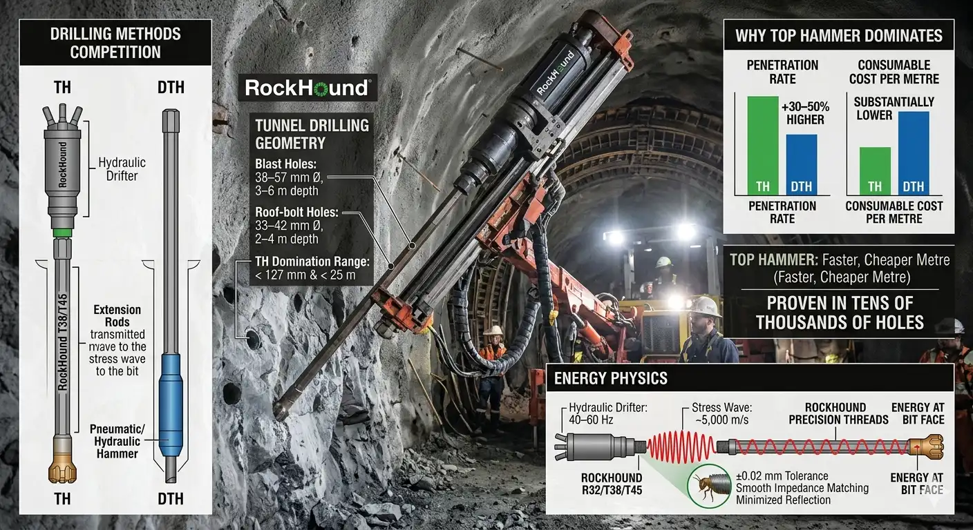
For holes under ~127 mm diameter and depths under 25 m, top hammer’s penetration rate is typically 30–50% higher than DTH, and consumable cost per metre is substantially lower—two advantages that compound across the tens of thousands of holes drilled over a multi-kilometre tunnel contract.
The energy physics are worth understanding briefly. A hydraulic drifter piston operating at 40–60 Hz launches a compressive stress wave that travels through the steel string at roughly 5,000 m/s. At every threaded joint, a fraction of that wave reflects back if the mechanical impedance (cross-sectional area × elastic modulus) changes.This is why thread type and rod-body diameter must be matched across the string.
RockHound’s R32, T38, and T45 rods are machined to tolerances of ±0.02 mm on the critical thread flanks, ensuring that impedance transitions are as smooth as the steel allows—keeping energy at the bit face, not bouncing back through the string.
Top Hammer Equipment: R32 R38 T45 Drill Rods
| Product Name | Type | L (mm) | L (inch) | H (mm) | H (inch) | Thread | Weight (KG) | Product Code |
|---|---|---|---|---|---|---|---|---|
| T45-46mm Speed MF Rod For Long-Hole Drilling | Extension | 1525 | 5 | 46 | 1 3/4 | T45 | 18.2 | 290-4615-7777 |
| 1830 | 6 | 46 | 1 3/4 | 21.5 | 290-4618-7777 | |||
| T45 Extension Round Rod For Long-Hole Drilling | Extension | 1525 | 5′ | 46 | 1 3/4 | T45 | 16.2 | 280-4615-7777 |
| 1838 | 6′ | 46 | 1 3/4 | 19.5 | 280-4618-7777 | |||
| R32 MF Rod For Long Hole Drilling | L 915-1830mm | Extension | 915 | 3′ | 32 | 1 1/4 | R32 | 5.5 | 290-3209-5454 |
| 1220 | 4′ | 32 | 1 1/4 | 7.3 | 290-3212-5454 | |||
| 1525 | 5′ | 32 | 1 1/4 | 9.0 | 290-3215-5454 | |||
| 1830 | 6′ | 32 | 1 1/4 | 10.5 | 290-3218-5454 | |||
| R38-H35-R32 Drifter Rod For Drilling L 3090–5525 | Drifter | 3090 | 10′ 1 21/32″ | 35 | 1 5/8 | R38 / R32 | 24.0 | 276-3530-5654 |
| 3700 | 12′ 1 1/2″ | 35 | 1 5/8 | 28.7 | 276-3537-5654 | |||
| 4305 | 14′ 1 3/64″ | 35 | 1 5/8 | 33.7 | 276-3543-5654 | |||
| 4915 | 16′ 1 1/2″ | 35 | 1 5/8 | 38.2 | 276-3549-5654 | |||
| 5525 | 18′ 1 33/64″ | 35 | 1 5/8 | 43.1 | 276-3555-5654 | |||
| R32-H28-R28 Threaded Drifter Rod For Tunneling | Drifter | 2600 | 8′ 6-3/8″ | 28 | 1 1/8 | R32 / R28 | 13.0 | 276-2826-5453 |
| 3090 | 10′ 1-5/8″ | 28 | 1 1/8 | 15.9 | 276-2830-5453 | |||
| 3700 | 12′ 1-5/8″ | 28 | 1 1/8 | 18.5 | 276-2837-5453 | |||
| 4005 | 13′ 1-43/64″ | 28 | 1 1/8 | 20.5 | 276-2840-5453 | |||
| 4265 | 13′ 11-1/2″ | 28 | 1 1/8 | 21.3 | 276-2842-5453 | |||
| 4305 | 14′ 1-31/64″ | 28 | 1 1/8 | 21.5 | 276-2843-5453 |
The Hydraulic Jumbo: Platform That Makes It Possible
A hydraulic jumbo is the machine that translates the raw power into a precisely positioned, series of blast holes covering an entire tunnel face. Modern two- and three-boom jumbos can cover cross-sections from around 12 m² in a narrow development heading to over 200 m² in a large cavern excavation. Each boom typically has six hydraulic control axes that position the drifter-and-feed assembly at any angle required by the drill pattern.
What distinguishes a high-end modern jumbo, from an older machine is not raw horsepower but intelligence. Current rigs from manufacturers such as Sandvik, Epiroc, and others incorporate computerised rig control systems (RCS) that store pre-loaded drill plans—full sets of hole coordinates, inclinations, and depths derived from the tunnel survey.
The operator confirms position against a laser or total-station reference, and the rig executes parallel positioning of multiple booms simultaneously. Automated parallelism control is particularly valuable for cut holes, where deviations of even 20–30 mm can compromise the void space that the parallel-hole cut depends on.
For the drill tooling manufacturer, this automation trend raises the specification bar. An automated rig will not stop drilling because a rod is worn or a shank adapter is fatigued—it runs at a consistent, high percussion frequency until a failure forces it to stop. That demands drill consumables engineered to outlast operator tolerance, not just meet it.
Surface hardness of 58–62 HRC on the shank body, tight control of inner-bore geometry to prevent stress-concentration fatigue cracking, and thread flanks that maintain geometry after thousands of make-break cycles are no longer desirable—they are the minimum entry qualification.
Hydraulic Jumbo Drilling Performance
manual vs. computerised operation (60 m² cross-section reference tunnel)
| Performance Indicator | Conventional Manual Jumbo | Computerised / Semi-Automated Jumbo | Source Basis |
|---|---|---|---|
| Average weekly advance (no support) | ~50 m/week | ~80 m/week | NTNU D&B model, 2007 edition |
| Drilling as % of blast-round cycle | 45–50% | 30–35% | NTNU advance rate model |
| Hole-position deviation (contour holes) | >5% of hole depth | <2% of hole depth | Field data, computerised jumbo studies |
| Typical blast-hole diameter range | 38–45 mm | 45–51 mm | Industry practice, tunnel projects |
| Drill productivity (m drilled/operator-hour) | Baseline | +30–40% above baseline | Tunnelingonline case data |
| Anti-jamming rod breakage reduction | — | Up to 35% fewer breaks (adaptive control) | Aivyter tunneling engineering analysis, 2025 |
Full-Face Drifting: Where the Cycle Begins
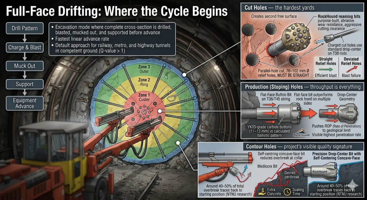
Full-face drifting is the excavation mode, where a complete tunnel cross-section is drilled, blasted, mucked out, and supported before the equipment advances. Compared with bench-and-heading or multiple-drift methods, it offers the fastest linear advance rate per working week—which is why it is the default approach for railway tunnels, metro bore tunnels, and highway tubes where the ground quality is competent (Q-value roughly above 1).
The drill pattern for full-face work divides the face into three functional zones: the cut, the production (stoping) area, and the contour perimeter. Each zone demands a subtly different tool specification, and getting that right is where project teams often leave money on the table.
Cut holes — the hardest yards
Because a tunnel face has only one free surface, the first blasted holes must create the second free surface that allows the rest of the round to break to. The parallel-hole cut achieves this with a group of large empty relief holes (typically 76–102 mm Ø) surrounded by smaller charged holes. Those relief holes must be drilled straight—genuinely, measurably straight—because the entire round’s performance depends on the void being in the right place.
RockHound’s reaming bits are purpose-built for the large-diameter relief holes: concentric button layouts sized to the host rod diameter, carburised flanks to resist the abrasive wear of the opening pass, and flush ports positioned to clear cuttings aggressively in the tight collar zone. The charged cut holes that surround the relief bore use standard drop-center bits on T38 rods—a combination that offers the parallel tracking needed when collaring in the compressed, stressed rock immediately adjacent to already-drilled holes.
Production holes — throughput is everything
The stoping holes that break rock between the cut and the contour zone,where penetration rate is most visible on the daily drilling report. Here a flat-face button bit on a T38 or T45 string typically outperforms a drop-center geometry because energy transfer to the face is more direct when there is no tendency for the bit to deflect—the rock ahead has already been freed on multiple sides by adjacent holes and the detonating cut. YK05-grade carbide buttons, sized 11–12 mm and arranged in a calculated ballistic pattern that prevents re-crushing chips, push ROP to its geological limit in this zone.
Contour holes — the project's visible quality signature
Perimeter holes define what the tunnel will look like for the rest of its operational life. A deviation that pushes one hole 50 mm outward in granite produces a ledge that costs concrete to fill and sometimes hours of manual scaling to make safe. Multiply that across hundreds of rounds over several kilometres and the cost differential between a mediocre bit and a precision drop-center bit becomes substantial.
The self-centring action of a concave-face bit at the moment of collar—when lateral forces are at their highest relative to penetration depth—is the single greatest mechanical contribution a bit can make to contour quality. It is not marketing language: NTNU contour quality research shows that around 40–50% of total overbreak traces back to the starting position of the contour hole, before any downhole deviation occurs. A bit that locks on correctly at collaring removes a large share of the problem before it can develop.
Contour Blasting: Controlling the Profile
Contour blasting—which encompasses both smooth blasting and pre-split blasting—is the technical discipline that governs how close the blasted tunnel wall sits to the design boundary. In railway and metro construction, the stakes are higher than in a typical road tunnel: clearance gauges are tighter, waterproofing systems are more sensitive, and the tolerances on concrete lining thickness are narrower. Any systematic overbreak directly increases the concrete volume needed for the lining, and that volume comes with a cost multiplier that grows as the tunnel lengthens.
The mechanism of smooth blasting is well understood: light decoupled charges in closely spaced perimeter holes, fired after the main production holes, create a stress field that guides fracture propagation along the line connecting the holes rather than penetrating deep into the remaining rock. Pre-split firing the perimeter holes before the main blast achieves a similar result by creating a parting plane that the main blast’s shockwave cannot cross.
Both techniques require holes that are consistently spaced and consistently straight. A smooth-blasting specification that calls for 500 mm hole spacing at 3.5 m depth falls apart if individual holes drift by 80–100 mm—suddenly the effective spacing varies from 400 mm to 600 mm along the string, and the crack-guiding effect weakens unpredictably. That is the direct, practical reason why contour-hole deviation below 1% matters: it is the prerequisite for the blasting technique to function as the designer intended.
Drill bit selection guide for tunnelling applications
| Bit Type | Optimal Ground | Key Performance Attribute | Primary Tunnel Use |
|---|---|---|---|
| Drop-center button bit | Jointed, interbedded, or variable rock | Self-centering collar; limits lateral wander in broken ground | Contour holes, smooth blasting perimeter |
| Flat-face button bit | Massive hard or very hard rock | Direct energy transfer; highest ROP in competent ground | Cut holes, production stoping holes |
| Retrac (step-gauge) bit | Soft, friable, or squeezing ground | Reaming geometry assists withdrawal without sticking | Probe holes, drainage holes, bolting in weak zones |
| Reaming / pilot-and-ream bit | All ground types | Enlarges pilot bore in a single pass; maintains straightness | Large-diameter relief holes in cut zone |
Roof Bolt Installation: Closing the Safety Loop Fast
Roof bolt installation—or rock bolt drilling more broadly—is the phase of a tunnel cycle that most directly controls worker safety in the hours after each blast. Under New Austrian Tunnelling Method (NATM) principles, the surrounding rock mass is expected to carry load through arch action, and systematic bolting mobilises that capacity by preventing block detachment and progressively locking the loosened zone before it can shed stress in an uncontrolled way.
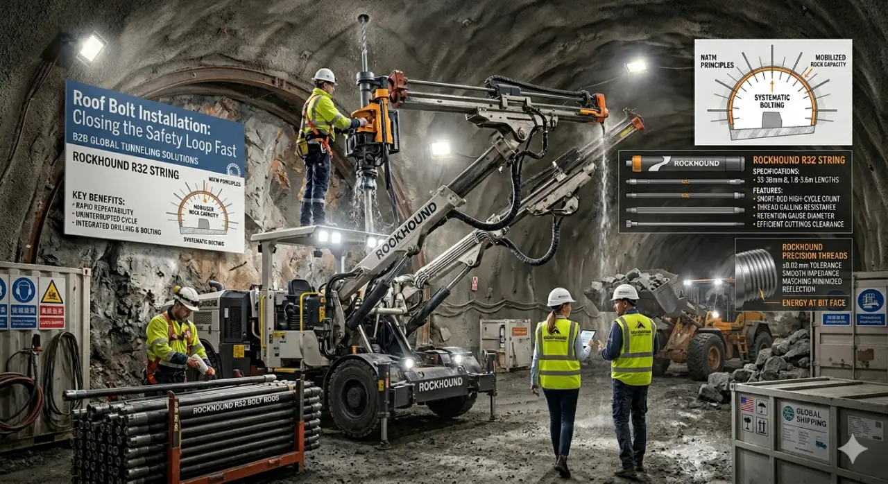
The operational tension is straightforward: the sooner bolts are installed after the face is scaled, the sooner the ground has tensioned reinforcement. Yet the time available is compressed—the mucking machine is clearing blasted rock, the next-round drill pattern needs to be set up, ventilation is still running hard. Roof-bolt drilling needs to be fast, repeatable, and capable of operating from the same hydraulic jumbo that drilled the blast holes, to avoid the time penalty of swapping equipment.
In practice, bolt holes run 33–38 mm in diameter at depths of 2.5–4 m in the crown and 3–6 m in the walls when longer systematic bolts are specified. That is a short-rod, high-cycle-count task: a typical 80 m² cross-section might need 25–40 bolts per round, drilled one after another at rapid-fire pace. The shank adapter must handle repeated short-string engagement and retraction without developing thread galling; the bit must retain gauge diameter for the full run because an undersize bolt hole causes installation problems that ripple downstream through the grout injection or mechanical expansion sequence.
RockHound’s lightweight bolt-hole rods—R32 string, 1.8–3.6 m lengths—combine the wall-thickness needed to survive repeated engagement cycles with a flush-through bore that clears cuttings efficiently even in the often-damp, partially supported conditions typical of a fresh tunnel excavation face.
Probe and Drainage Hole Drilling: Looking Ahead to Stay Safe
Probe and drainage hole drilling is one of the most intellectually honest practices in underground construction—it is the explicit admission that the ground ahead is uncertain, and that spending a few hours getting reliable information is cheaper than dealing with a surprise inrush. It is standard practice in Scandinavian tunnelling, increasingly mandatory on contractually challenging projects elsewhere, and practically universal wherever karst geology, faulted zones, or urban proximity raises the stakes on an unexpected water encounter.
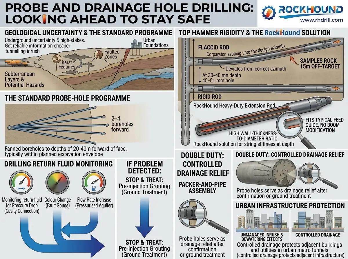
The standard probe-hole programme sends two to four boreholes forward at shallow fan angles—typically staying within the planned excavation envelope—to depths of 20–40 m ahead of the working face. The drilling fluid return is monitored for pressure drop (indicating a cavity connection), colour change (indicating fault gouge), or flow rate increase (indicating a pressurised aquifer). If the probe indicates a problem, the face stops and ground treatment—usually pre-injection grouting—takes place before excavation continues.
The top hammer tool system for this task is more demanding than it looks. At 30–40 m depth on a 45–51 mm hole, string stiffness matters. A flaccid rod bends under gravity and produces a hole that curves gradually away from the design azimuth—meaning the probe samples rock 15 m to one side of where the engineer thinks it is, exactly negating the purpose of the exercise. RockHound’s longer heavy-duty extension rods for probe work use a higher wall-thickness-to-diameter ratio than standard drifting rods, balanced against a diameter that still fits in the feed guide of a typical two-boom jumbo without boom modification.
Once ground conditions are confirmed benign—or after treatment is complete—the same probe holes often serve double duty as drainage relief. Leaving them open or fitting packer-and-pipe assemblies allows seepage to drain ahead of the face rather than building pore pressure. In urban metro tunnels where nearby building foundations or utilities are sensitive to ground water changes, this controlled drainage also protects adjacent infrastructure from dewatering effects that an unmanaged inrush would cause in a far less controlled way.
Economic Analysis: Drilling Tool Quality as a Leverage Point
The commercial case for investing in precision drill tooling is sometimes obscured by the line-item visibility of consumable costs. A premium shank adapter costs more per unit than a commodity equivalent. What that unit-cost comparison misses is the chain of effects that a failed shank adapter or a deflecting bit set in motion—lost penetration rate, extra rod changeovers, redrilling of deviated holes, higher concrete volumes from excess overbreak, and the schedule delay cost that attaches to every hour of unplanned downtime.
Research Context
According to NTNU productivity research, mechanisation improvements between 1975 and 2005 lifted advance rates for a 60 m² road tunnel from ~50 m/week to ~80 m/week—a 60% improvement—while unit excavation costs fell by 36%. That gain was not delivered by cheaper tooling; it was delivered by better-performing tooling running on more capable machines.
Blast-round cycle time breakdown
Typical railway tunnel, 70–90 m² cross-section
| Activity | Typical Share of Cycle | Primary Influence Factor |
|---|---|---|
| Drilling | 30–35% | Tool penetration rate (ROP), drifter power, number of booms |
| Loading / mucking and haulage | 22–26% | Blast fragmentation quality, loader and truck capacity |
| Charging and firing | 13–15% | Hole accuracy, explosives type, initiation system |
| Rock support (bolts + shotcrete) | 12–16% | Bolt-hole drilling speed, ground quality, support class |
| Scaling and face inspection | 10–13% | Contour blasting quality, overbreak level |
| Ventilation clearance | 3–5% | Explosive type, tunnel length, fan capacity |
Two activities in that table—drilling and rock support—together account for roughly half the cycle and both are directly influenced by the quality of the drill tooling used. A 10% improvement in penetration rate cuts about 3–4% off the total cycle time; a well-controlled contour reduces scaling and shotcrete prep, potentially saving another 5–8% of the cycle in well-blasted ground. Together that is a meaningful schedule acceleration on a multi-year infrastructure contract.
Application summary: top hammer tooling by tunnel drilling task
| Drilling Task | Typical Hole Ø | Depth Range | Recommended Thread | Recommended Bit Type | Key Specification Driver |
|---|---|---|---|---|---|
| Parallel-hole cut (relief) | 76–102 mm | 3.0–5.5 m | T51 / T60 | Reaming bit (pilot + ream) | Hole straightness ≤0.5% |
| Parallel-hole cut (charged) | 45–51 mm | 3.0–5.5 m | T38 / T45 | Drop-center button bit | Parallelism with relief holes |
| Production (stoping) holes | 45–51 mm | 3.0–5.5 m | T38 / T45 | Flat-face button bit | Maximum ROP |
| Contour (smooth blasting) | 45–51 mm | 3.0–5.5 m | T38 | Drop-center button bit | Hole deviation <1% |
| Roof bolt holes | 33–38 mm | 2.0–4.5 m | R32 | Retrac or drop-center, small gauge | Full gauge retention; cycle speed |
| Probe / drainage holes | 45–51 mm | 20–40 m | T38 / T45 | Retrac button bit | Hole straightness over long depth |
Automation, Data, and the Next Generation of Tunnel Drilling
The steady march toward autonomous drilling does not change the physics of rock breaking, but it does change what is expected of the consumables carrying that physics into practice. Automated three-boom jumbos running 20 ft drifter rods can achieve 800–1,200 feet of drilled hole per hour—a rate no manual system can sustain across a full shift. At those intensity levels, a rod with a marginal fatigue life does not fail gracefully; it fails mid-hole during an automated run, and the machine has no obvious way to detect it until the drill string suddenly has less than expected compliance.
Condition monitoring is closing that gap. Vibration sensors on the drifter housing, penetration-rate deviation alerts, and torque-spike logging are now standard features on Level 3 and Level 4 autonomous rigs. But the sensor data is only as useful as the baseline it is compared to—which means the quality consistency of the drill string must itself be consistent. Batch-to-batch variation in shank adapter hardness, or inconsistent thread-flank geometry from a low-quality supplier, introduces noise into the monitoring data that can mask real wear signals or trigger false stops. Tight manufacturing tolerances are, in this sense, a prerequisite for the automation investment to deliver its promised return.
Electric-drive jumbos are also making inroads in urban metro and railway tunnel projects, particularly where diesel-exhaust limits are enforced in long tunnels with limited ventilation capacity. The shift to electric drive removes one noise source from the signal chain—steady hydraulic flow versus the variable output of a diesel hydraulic pack—and may further improve the fidelity of in-process drill monitoring.
Conclusion
Mechanised tunnelling is a precision manufacturing process running underground. Each blast round is a production cycle, and like any production cycle, its output quality and speed are governed by the quality of the tools that execute it. Top hammer drill consumables—shank adapters, extension rods, and button bits—occupy the critical interface between machine power and rock mass; they cannot compensate for a bad blast design or a failing jumbo, but an optimised tooling system extracts the full potential that the machine and design have set up.
The specific demands of tunnelling—straight contour holes for profile control, fast short-string cycling for roof bolting, long-depth accuracy for probe drilling, and consistent impedance matching for high-frequency automated jumbos—are not generic. They require tooling specified and manufactured for those tasks rather than adapted from a mining or quarry catalogue. RockHound’s engineering focus on tight thread tolerances, high-toughness core metallurgy, and drop-center geometry selection is built around that specificity.
For project teams evaluating tooling for a coming railway, metro, or highway tunnel contract, the right question is not “what does this shank adapter cost per unit?” but “what does this shank adapter cost per metre of advance, and what is its contribution to overbreak, cycle time, and bolt-hole quality?” Those metrics, benchmarked honestly against your ground conditions and jumbo specification, are where the real value conversation starts.
Ready to Discuss Your Tunnel Project Tooling?
RockHound’s technical team works with project engineers and procurement managers to match tool specifications to ground conditions, jumbo type, and advance-rate targets. Contact us for a project-specific consultation.
Frequently Asked Questions
Full-face drifting excavates the complete tunnel cross-section in a single blast round, rather than splitting the face into multiple sequential headings. A hydraulic jumbo is essential because its two or three independently controlled booms can position drill steels simultaneously across the full face, maintaining the hole-placement accuracy that a single-man pneumatic approach cannot achieve at scale. Cross-sections from 12 m² to over 200 m² are covered by commercially available jumbo platforms.
Conventional production blasting optimises fragmentation and muck-pile condition for efficient loading. Contour blasting—covering both smooth blasting and pre-split blasting—prioritises the geometry of the remaining rock wall. It uses closely spaced, lightly loaded perimeter charges to steer fracture propagation along a designed boundary, minimising overbreak and leaving a stable, undamaged rock surface. In railway and metro tunnels, the finished wall quality directly affects waterproofing system performance and concrete lining thickness—making contour discipline an economic issue, not just a technical one.
Drop-center (concave-face) button bits are the preferred choice for contour holes. The recessed face geometry self-centres against the rock surface at collaring—the phase when lateral deviation risk is highest—and maintains a consistent guidance trajectory through jointed or laminated ground. For most railway and metro specifications, this keeps hole deviation below the 1% of depth threshold that smooth blasting requires to function reliably.
The dominant thread systems for hydraulic drifter rods in tunnelling are R32, T38, and T45. R32 is standard on lighter single-boom rigs used in smaller development headings. T38 is the workhorse for medium to large tunnel cross-sections, balancing rod section modulus with acceptable weight for multi-extension strings. T45 is reserved for high-energy drifters (30 kW and above) where impact frequency and string length would otherwise overload a T38 connection at the thread flanks.
Probe drilling provides advance intelligence about the ground 20–40 m ahead—information that cannot be reliably inferred from surface investigation data alone, particularly in folded geology, karst limestone, or urban settings where ground modification from adjacent construction can create unexpected conditions. A pressurised water pocket encountered without warning can flood a tunnel heading in minutes; the same condition identified by a probe hole two rounds in advance is a managed drainage and grouting task. The cost ratio between those two outcomes is enormous, which is why probe drilling is treated as non-negotiable on most major infrastructure contracts.
Top hammer places the drifter at the surface end of the string and transmits impact as a stress wave through extension rods; DTH positions the hammer directly behind the bit at depth. For the hole diameters and depths that dominate tunnel blast-hole and rock-bolt work (38–57 mm, 2–6 m), top hammer is faster and significantly cheaper per metre because energy transmission losses at those depths are modest. DTH becomes preferable beyond roughly 127 mm diameter or 25 m depth, where transmission losses in a top hammer string become a meaningful efficiency penalty.
Yes. Modern multi-boom jumbos are routinely used for both tasks within the same cycle. Operators swap to a shorter R32 rod string and a lighter shank adapter for bolt-hole work, keeping the same drifter on the boom. Dedicated single-boom bolting rigs offer faster cycle time for high bolt-count specifications, but the additional mobilisation cost is only justified in rock conditions that require dense bolting patterns—typically Q-class below 1 or designated NATM support classes E4 and E5.